Will Not Cycle
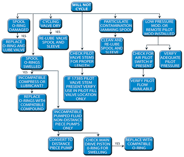
WILL NOT CYCLE:
SYMPTOMS:
Air pressure to the drive does not cause the booster to start
cycling.
THEORY OF CAUSE:
The air drive pressure is used for driving the main air piston and
for shifting the cycling valve by pressurizing and venting the
pilot system cavity. Because of the large forces involved with
the air drive piston, it is unlikely to be the cause of the
inability to cycle. The cycling spool, using relatively low
pressure and small surface areas, has very low forces driving it.
Therefore it does not take much restraining force to stop it.
The most common causes of inability to cycle are as follows:
a. Drying out of lubrication on the spool “O” rings due to an
extremely “dry” air supply.
b. Washing out of the lubrication on the spool “O” rings due to
excessive water in the air supply.
c. Contamination in the air cycling valve sleeve causing the
spool to be “jammed” by particulate interference.
d. Swelling or damage of “O” rings due to presence of
“incompatible” gases. (i.e.- Sour gas, carbon dioxide, etc.)
e. If the pilot valve stems are too short and do not get enough
travel to open properly, it can also cause an inability to
cycle. This condition usually occurs after an overhaul,
where there are two different length pilot stems that have
accidentally been switched.
f. Lack of a separate pilot pressure source for pumps equipped
with the “remote pilot modification”. It can also happen if the
unit is equipped with an air pilot switch that is “normally
closed” and set to open at some higher pressure.
TROUBLE SHOOTING METHODS:
For items a and b, remove retaining cap and cycling spool and
inspect “O” rings for wear or damage. Replace “O” rings as
required. Re-lubricate with Haskel lubricant (from seals kit),
and re-assemble.
For item c, remove retaining cap, spool and sleeve, and clean thoroughly with solvent. Inspect for “O” ring damage. Replace seals as required. Re-assemble with Haskel lubricant.
For items d, determine if “O” ring seals have been swelled by compressor air. Determine what is the proper “O” ring compound that will satisfactorily resist this fluid, and replace seals, lubricate and re-assemble.
For item e, check assembly drawing to verify proper location of stems. Switch stems, if necessary, to verify proper placement.
For item f, verify whether a “remote pilot” modification has been installed in the pump. Usually, this deletes the 1/8” plug located just adjacent to the 1/2” pipe plug at the end of the cycling valve. If that port is open, it most likely needs a separate pilot air pressure supply to match the drive pressure (or 40 psig minimum with the “low pressure” modification).